
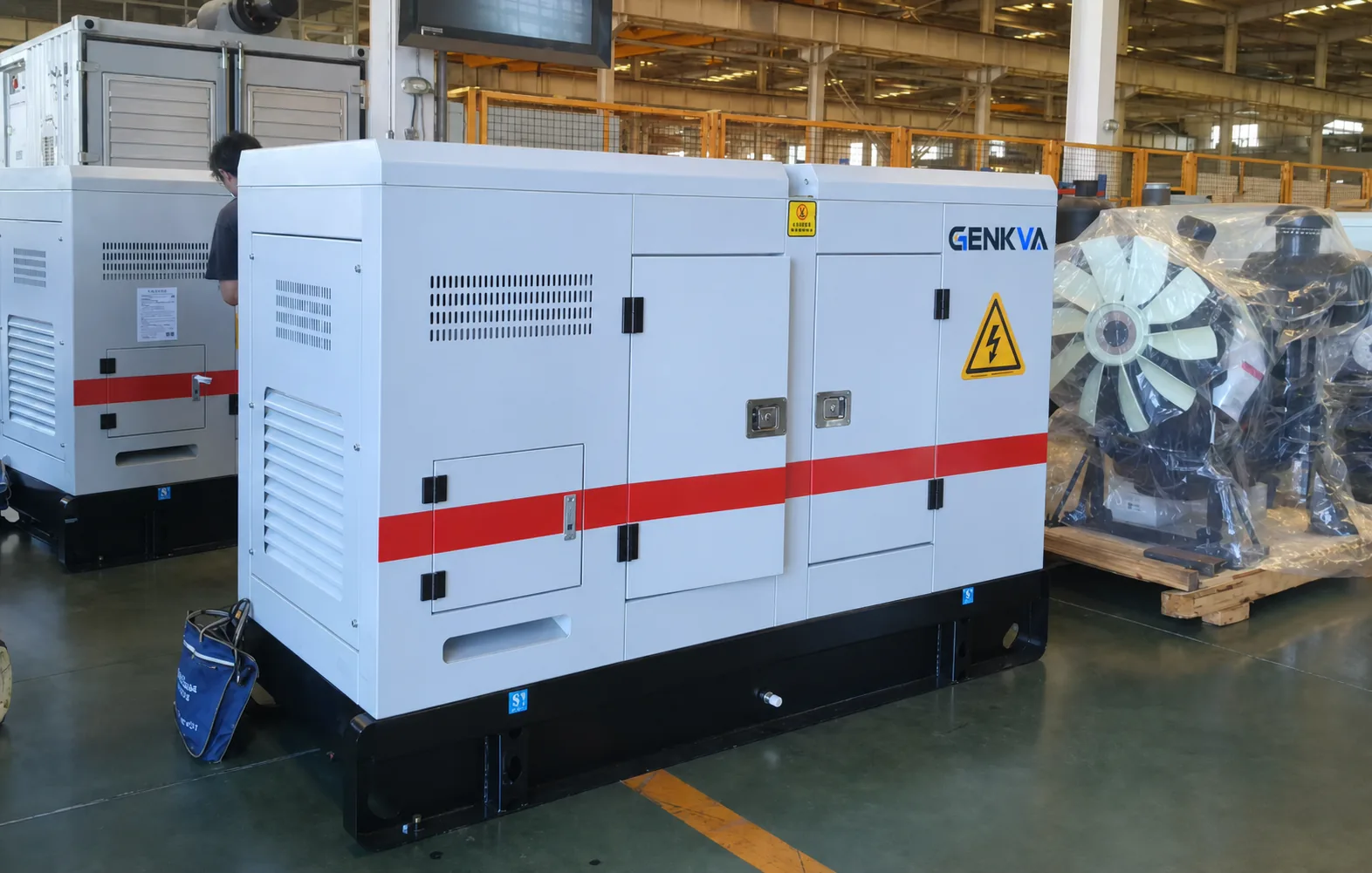
First, define what the factory test must prove
Before the test, freeze the rating and duty, voltage, frequency, power-factor basis, engine, alternator, controller, breaker, enclosure, cooling, fuel system, starting system, and included accessories. Also approve the load-bank type, sequence, duration, measured channels, acceptance criteria, witness method, deviation process, and records required for shipment release.
Do not import a generic test recipe
There is no safe universal load percentage, test duration, step sequence, or tolerance for every generating set and application. The contract, approved manufacturer data, project specification, applicable standard, and qualified engineering review control the test.
Write the acceptance question in one sentence: “Does this exact generator set, in its approved factory-test configuration, carry the specified load sequence and perform the agreed controls and protections within the documented acceptance limits?” That is narrower than asking whether the complete installed emergency-power system will work at site.
ISO 8528-6:2023 specifies test methods for characterizing an entire reciprocating-engine-driven AC generating set and notes that supplementary requirements may be needed for specific applications. ISO 8528-5:2025 addresses design and performance criteria arising from the engine-generator combination. The purchased editions, contract, manufacturer declarations, and project requirements still control the actual FAT.
A factory load bank can apply a controlled electrical load and help observe steady and transient generator-set behavior. It may not reproduce the site cables, transfer equipment, switchgear, grounding, fuel system, ventilation, altitude, ambient temperature, nonlinear loads, motors, UPS systems, harmonics, protection coordination, building-management interfaces, or operator actions.
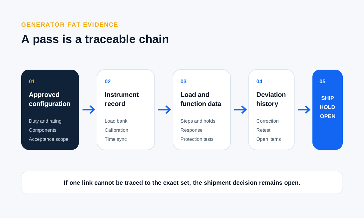
Records 1–2: freeze the scope and identify the exact test article
1. Approved FAT scope and configuration record
Ask for a signed scope that identifies the purchase order, approved drawings, generator model, rating category, rated kW and kVA, voltage, phase, frequency, speed, power-factor basis, engine, alternator, controller, breaker, enclosure, cooling arrangement, starting system, fuel configuration, and accessories present during the test.
The record should state every difference between the tested article and shipment configuration. If a production controller, radiator, breaker, exhaust system, battery, charger, enclosure, or accessory is simulated or omitted, identify how that changes the evidence and what later test closes the gap.
2. Test article and component traceability record
Request the generator-set serial number plus the engine, alternator, controller, and major accessory identifiers available under the approved quality plan. Include the relevant software or parameter version, protection settings, wiring revision, and nameplate data.
Photographs can support identity, but they should not carry it alone. If a component changes after the test, require a disposition: accept the existing evidence with written engineering rationale, repeat affected checks, or repeat the FAT.
Records 3–4: make the measurements reproducible
3. Load bank and instrument record
Identify the load bank, whether the applied load is resistive, reactive, combined, regenerative, or another approved simulation, its connection arrangement and available steps, plus the equipment used to measure current, voltage, frequency, power, power factor, temperatures, pressure, insulation, sound, or emissions when those channels are in scope.
Record instrument identifiers, ranges, accuracy or uncertainty basis where required, and calibration status valid for the test date. State the sampling or logging interval and time synchronization. Without that information, a plotted line may look precise while remaining impossible to reproduce.
4. Ambient conditions and derating-basis record
Capture the test location, date and time, ambient temperature, barometric pressure or elevation basis when relevant, humidity when required, fuel properties used by the approved plan, ventilation condition, and coolant or inlet conditions. Record the manufacturer reference conditions and any correction or derating method applied.
A favorable factory result does not automatically establish site capacity at high altitude, high ambient temperature, restricted airflow, or another fuel quality. Link the FAT to the approved site calculation; GENKVA’s generator derating guide owns that separate decision.
Records 5–6: preserve readiness and time-sequenced response
5. Pre-start inspection and readiness record
Before loading, record fluid levels, leaks, battery and charger status, cooling path, guards, connections, the test grounding arrangement, exhaust condition, emergency-stop reset, alarms, shutdowns, breaker state, controller configuration, and the visual and mechanical inspection results required by the plan.
Show initial readings and open issues. Do not erase a corrected problem from the history. A useful FAT package records what was found, what changed, who accepted the correction, and whether it affected later measurements.
6. Time-sequenced load-step and response record
Require a time sequence for each commanded load step, ramp, hold, unload, and recovery. For every interval, capture the channels required by the plan—commonly voltage, frequency, phase currents, kW, kVA, power factor, engine speed, oil pressure, coolant temperature, exhaust or winding temperatures when instrumented, fuel observations, and controller status.
Transient acceptance depends on the application and approved performance class. Record the pre-step condition, applied step, minimum or maximum excursion, recovery definition, recovery time, and stable value when required. A table containing only “25%, 50%, 75%, 100% — pass” hides the response buyers usually need to evaluate.
Do not assume a resistive load bank reproduces a large motor start, transformer energization, UPS input, rectifier, or another nonlinear or reactive load. Define reactive or dynamic simulation when the project requires it and leave site-specific integrated behavior for commissioning.
Records 7–8: capture operating observations and functional checks
7. Steady-state observations and thermal record
At each required hold point, record stable electrical readings and the observations named in the plan: leaks, vibration, abnormal sound, smoke or exhaust condition, cooling behavior, fluid pressure, temperature trends, enclosure airflow, hot spots, or sound readings. Use thermal images or sound measurements only when the method, location, instrument, operating condition, and acceptance rule are approved.
The U.S. Army Corps of Engineers commissioning guidance says generators should be factory load tested and discusses shutdown and alarm monitoring, sound, temperature or thermal checks, and megger testing. That supports a broader FAT evidence package, but it is not a universal commercial specification; select checks from the project requirements.
8. Controls, protections, alarms, and interfaces record
List every function included in FAT: start and stop modes, emergency stop, breaker operation, alarms, shutdowns, sensors, remote signals, automatic controls, paralleling functions, load sharing, synchronizing, communications, or simulated external commands. Record the trigger, expected response, actual response, reset method, and result.
Where a site device is unavailable, identify the simulator and test boundary. A dry contact changing state at the controller does not prove the field cable, building system, transfer switch, switchgear, utility interface, or complete sequence. Put those items in a site test matrix with a named owner.
Record 9: keep deviations, corrections, retests, and release visible
Every failed, interrupted, repeated, or invalid test should remain visible. Record the issue ID, observation, affected requirement, root cause or current diagnosis, correction, parts or setting changed, approval, retest scope, retest result, residual risk, and whether the change altered the approved configuration.
Shipment release should be a separate signed decision. Use three outcomes: accepted for shipment; accepted with named open items and owners; or shipment on hold. Attach the final configuration freeze, packing and preservation checklist, document index, open-item register, and the tests that remain for site commissioning.
A retest after correction can support acceptance when the affected scope and configuration are clear. It should not overwrite the first result or silently narrow the acceptance criteria.
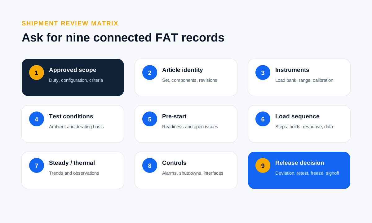
Put the nine FAT records into one review matrix
| FAT record | Buyer checks before test | Shipment-release evidence |
|---|---|---|
| Scope and configuration | Approved duty, ratings, options, test method, and criteria | Signed scope and exact test versus shipment configuration |
| Traceability | Required set, component, software, and setting identifiers | Serial, revision, and setting record tied to results |
| Instruments | Required channels, ranges, sampling, and calibration | Equipment list and valid status for the test date |
| Conditions | Factory ambient and approved derating basis | Logged conditions and documented correction method |
| Pre-start | Inspection and readiness checklist | Initial readings, open items, and dispositions |
| Load sequence | Steps, holds, unload, and transient measurements | Time-synchronized data and calculated results |
| Steady and thermal | Required observations and measurement locations | Trends, images, or readings with method and conditions |
| Controls and protection | Functions, triggers, expected response, simulator boundary | Actual response and reset record |
| Deviations and release | Issue, correction, and retest process | Complete issue history, retest, and signed release status |
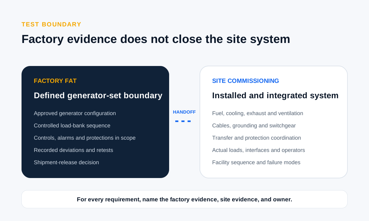
Keep factory FAT and site commissioning separate
Factory acceptance proves the defined generator-set configuration under the approved factory test. Site commissioning verifies the installed equipment, fuel, ventilation, exhaust, cables, grounding, switchgear, transfer sequence, protection coordination, communications, actual loads, operators, and facility conditions. Integrated testing verifies the full operating sequence and failure modes required by the project.
Create a boundary table with four columns: requirement, factory evidence, site evidence, and owner. Do not close a site requirement merely because a related factory check passed. Conversely, do not repeat a valid factory measurement at site without a reason; focus field work on installation and system interactions.
Use GENKVA’s commissioning support page to prepare site inputs. Keep quotation comparison in the generator quotation guide and preliminary capacity work in the kW and kVA sizing resource.
Send a testable FAT request
Include the generator duty, load schedule, largest steps, voltage, phase, frequency, power factor, altitude, ambient temperature, fuel, enclosure, cooling, noise requirement, controller, breaker, communications, applicable standards, witness method, record format, deviation process, and site-test boundary in the RFQ or purchase order.
Ask for scope before asking for a pass
Ask GENKVA to identify the included, optional, excluded, simulated, and site-only checks for the exact model and configuration. A responsible FAT proposal cannot promise a universal result before the acceptance criteria are approved.
Request a generator FAT reviewGenerator load-bank FAT FAQs
Is a factory load-bank test the same as site commissioning?
No. Factory testing verifies the defined generator-set configuration under controlled factory conditions. Site commissioning verifies the installed fuel, ventilation, exhaust, cables, grounding, switchgear, transfer and control sequences, communications, actual loads, operators, and site conditions.
Does a resistive load bank prove motor or UPS performance?
Not necessarily. A resistive bank applies real-power load but may not reproduce reactive current, harmonics, inrush, regeneration, power-electronic behavior, or the actual operating sequence. Define the required simulation and validate site-specific interactions separately.
What load percentage and duration should be used?
There is no universal answer. Use the approved manufacturer data, rating and duty, application load profile, applicable standard, contract, project specification, and qualified engineering review to define the steps, duration, and acceptance limits.
What should a generator load-bank report contain?
It should connect the approved scope, exact test article, instruments and calibration, conditions, pre-start state, time-sequenced load and measured channels, controls and protections, observations, deviations, retests, final configuration, and signed release status.
Can shipment be released after a failed test is corrected?
It can be considered when the deviation, cause, correction, affected configuration, approved retest scope, retest evidence, open risks, and approving authority are fully documented. The original result should remain visible, and shipment release should be a separate signed decision.
Sources and scope
- ISO 8528-6:2023 — Test methods
- ISO 8528-5:2025 — Generating sets
- ISO 8528-7:2017 — Technical declarations for specification and design
- U.S. Army Corps of Engineers EM 1110-2-3105
This buyer checklist does not replace the purchased standards, contract, model data sheet, project specification, authority requirements, site risk assessment, or qualified electrical and mechanical engineering. It deliberately avoids universal numeric acceptance limits and reports no unverified factory result.